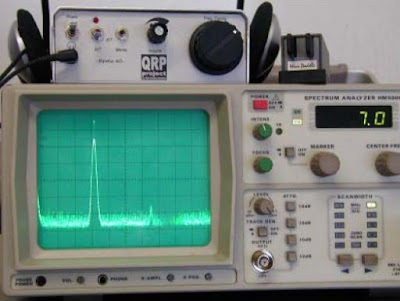
The Spatz (German Spatz) is a small monoband CW transceiver kit designed by DK1HE and distributed in kit form by the German QRP Project. Despite the small size and relative simplicity of the kit, the Spatz is a quite advanced transceiver featuring goodies like DDS with RIT/XIT, 8 pole Cohn Filter with 400Hz bandwith, AGC with high dynamic range, heavy duty PA, built-in keyer and full QSK. The kit can be bought with DDS ready built and tested and is available for the 80, 40, 30, 20 and 17 meter bands.
Specifications (40m version)
| Frequency coverage | 7.0 – 7.1 MHz |
| Tuning steps | 1Hz, 30Hz, 100Hz, and 1kHz |
| VFO type | DDS with AD9835 |
| Modes | CW |
| RX type | Single conversion with 4MHz IF |
| RX sensitivity | 0.3 μV |
| IF filter | 8 pole Cohn with 400Hz width |
| Dynamic range | 90 dB (IF+AF) |
| RIT | ? kHz |
| XIT | ? kHz |
| TX power out | 5W |
| CW keyer | 10 – 40 wpm |
| RX power consumption | 80 mA |
| TX power consumption | 630 mA (at 5W out) |
Functional Description
The Sparrow is based on a traditional transceiver design with local oscillator, superheterodyne receiver and a transmitter section, but it also includes some bells and whistles only found in more advanced designs.
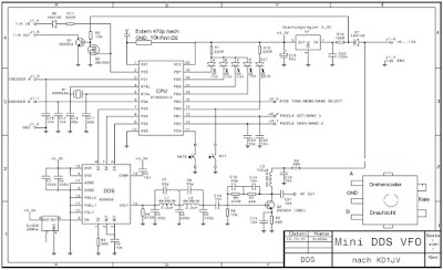
The local oscillator contains a DDS VFO using an AD9835 chip as synthesiser and an AT90S2313 microcontroller to control the DDS chip. Besides frequency control, the microcontroller also implements a iambic keyer as well as RIT/XIT and a memory channel. The DDS generates 8.0 to 8.1 MHz, which mixed with the signal from a 3 MHz crystal oscillator results in 11.0 to 11.1 MHz local oscillator
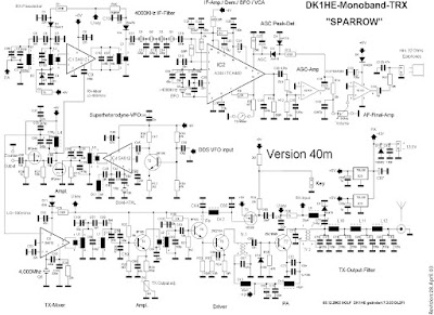
The receiver uses the TX low pass filter and a simple bandpass filter at the input, whereafter the received signal is mixed with the 11 MHZ local oscillator using a SA612. The 4 MHz IF signal is then passed on to an 8 pole Cohn crystal filter with 400 Hz bandwith. This is very good for CW work. After the crystal filter follows the IF amplifier, demodulator, BFO and audio preamplifier, all of which are done by a single TCA440 chip. After the audio preamplifier follows the AGC amplifier based on a single op-amp and the AGC signal is fed back to the TCA440 controlling both the IF and audio preamp gains. The TCA440 has the possibility to attach a signal strength meter. After the AGC preamp there is the final audio amplifier consisting of a single opamp, which is adequate to drive a pair of earphones.
The transmitter section begins with a mixer very similar to the first mixer in the receiver (SA612). After the mixer and a set of bandpass filters comes a pre-amplifier with variable gain using a BF199 transistor. The gain of this amplifier determines the output power of the sparrow and can be adjusted from close 0 watts up to more than 15 watts. After this amplifier follows the driver (BF199 + 2N2210A) and the power amplifier. The PA section is a class C amplifier and uses a rather powerful 2SC1969 transistor. By using this powerful transistor at 5 watts or less, the PA stage becomes very robust to mismatched antennasand other unfortunate events. The antenna input/output of the sparrow is 50 ohms and the transmitter harmonics are reduced by at least 50 dBc using a three section lowpass filter.
Besides the above mentioned circuits there are some miscellaneous circuits for keying, T/R switching and voltage regulator. The most interesting of these is the T/R switching circuit which uses no relays at all and allows true click-free full QSK. You can see the schematic diagram below.
More articles about the Sparrow 40 in the article index.


